Time to read: 6 min
Hard tooling by μEDM-milling for injection molding
4 Injection Molding
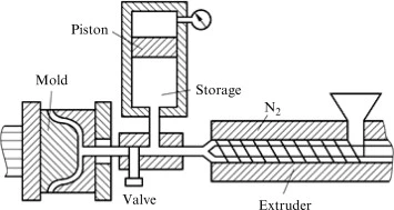
Injection molding is a key technology for the economic production of microstructures. This technology enables a low-cost mass production of micro structured parts [5, 6]. The characterized mold inserts can be replicated by injection molding. For this replication process, we constructed an injection tool in which we can easily and quickly change the mold insert. Figure 7 shows the injection molding tool with the exchangeable mold insert.
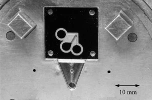
Fig. 7. Injection molding tool with exchangeable mold insert.
The injection molding machine (Microsystem 50, Battenfeld) used in this study is a fully electric machine for the precise production of micro structured moldings. For testing of mold inserts, an industrial grade COC (Topas 5013 and 6013, Ticona GmbH) is used to produce structured chips. The injection molding tool is designed with a flow runner. In the area of the runner, a pressure sensor is integrated for controlling process parameters. The molding tool is heated up to 120 °C. The process starts with the injection of the molten mass into the cavity using an injection plunger [7]. After injection, the post pressure avoids shrinkage during freezing of the polymer. To eject the molded chip, the molding tool is opened and the ejectors push out the chip automatically. After the ejection the next production cycle can start. The parameters of the injection molding process for producing the sample chips are listed in table 2.
Table 2. Parameters of the injection molding process.
| Parameter | Quantity/value |
|---|---|
| max. injection pressure | 700 bar |
| cycle time | 40 sec |
| mass temperature | 300 °C |
| tool temperature | 120 °C |
| injection volume | 440 mm3 |
In figure 8 a top view of an injection molded plastic chip consisting of COC polymer is represented.
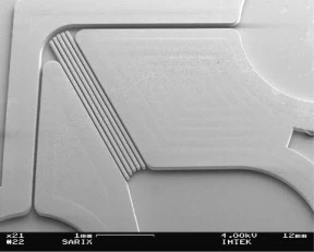
Fig. 8. SEM micrograph of the replicated plastic chip.
Figure 9 shows a cross section of some parallel PC channels. The mould was filling completely.
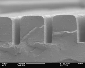
Fig. 9. Cross section of the PC channels.
Chapter
Processing of Polymers and Their Composites: A Review
Injection Molding
Injection molding is a technique to transfer polymer materials into useful products of various shapes. It is a cost-effective method, and can produce complex shape parts not only with a high precision but also at a high production rate. Fig. 3 shows the schematic diagram of injection molding process which comprises a hydraulic unit, injection unit and clamping unit.

Fig. 3. Schematic diagram of injection molding machine. Reproduced from Yang, Y., Gao, F., 2000. Adaptive control of the filling velocity of thermoplastics injection molding. Control Engineering Practice 8 (11), 1285–1296.
High production rate of injection molding process is closely associated with injection velocity. Yang and Gao [24] used an adaptive controller to control the injection velocity. The pole-placement technique was found to be suitable for different molding conditions. Shrinkage is the problem that is associated with injection molding process. If a hollow or a partially hollow part is to be produced by using injection molding technique then water assisted or gas assisted injection molding can overcome the problem of shrinkage. Although, process cycle for gas and water assisted injection molding is almost same, water assisted injection molding have several advantages over gas assisted injection molding. The cooling cycle of water assisted injection molding technique is less than gas assisted injection technology because of high thermal conductivity of water. Compaction of water is higher than that of gas because water is incompressible in nature. Water injection technology (WIT) can produce part with high internal surface than gas assisted injection molding. When the water is injected into the melt, its viscous front acts as a ram and this viscous front forces the molten material forward, and eventually helps to reduce defects in the final part [25].
Water assisted injection molding technology is of two types, partially filled (short-shot molding) and fully filled (full-shot molding) mold with polymer melt. After filling the polymer melt into the mold, water is injected into the core of polymer melt. The schematic diagram of water assisted injection molding is shown in Fig. 4.
Fig. 4. The setup for water-assisted injection-molding. Reproduced from Liu, S.-J., Chen, Y.-S., 2004. The manufacturing of thermoplastic composite parts by water-assisted injection-molding technology. Composites Part A: Applied Science and Manufacturing 35 (2), 171–180.
Liu and Chen [26] used Taguchi method to optimize the process parameters of water assisted injection molding for thermoplastic composites. Optimization of parameters was done on the basis of length of water penetration into the core. In conventional injection molding process polymer melt starts to cool very rapidly as it enters the mold cavity and the molded part then undergoes a shrinkage. In water assisted injection molding water penetrates into the core of polymeric melt and pushes it against the mold wall which helps to minimize the shrinkage. Short-shot size were found to be significant parameter which affect the length of penetration. Liu and Chen [27] investigated the design of water injection pins. As the polymer melt is forced into the mold cavity, melt could stick to the small opening of water injection pins. Two type of rings were selected to study this behaviour. Result showed that ring type water pins have very less chance of sticking by polymer melt. However, due to limited volumetric flow rate the possibility of incomplete filling is severe. On the other hand the possibility of sticking of orifice type pins is very high. However, its larger hole diameter leads to complete filling of mold.
Thin wall injection molding has many applications in electronic industry especially in micro-electro-mechanical systems. However, injection molding process for manufacturing parts with very low thickness is difficult and complicated. Song et al. [28]used Taguchi method to investigate the different process parameters as shown in Table 2. Table 3 shows the results of the filling area with respect to different parameters of injection molding process.
Table 2. Levels table of factors
| Empty Cell | Level 1 | Level 2 | Level 3 |
|---|---|---|---|
| Factors | Levels | ||
| A: Injection rate (ν) (mm/s) | 60 | 84 | 108 |
| B: Injection pressure p (MPa) | 85 | 95 | 105 |
| C: Melt temperature θ (°C) | 220 | 230 | 240 |
| D: Metering size h (mm) | 7.0 | 7.5 | 8.0 |
| E: Part thickness δ (mm) | 0.2 | 0.1 | – |
Note: Song, M., et al., 2007. Research on effects of injection process parameters on the molding process for ultra-thin wall plastic parts. Journal of Materials Processing Technology 187, 668–671.
Table 3. Project and results of experiment
| No. | A: (ν) (mm/s) | C: θ (°C) | Empty Cell | B: p (MPa) | D: h (mm) | Empty Cell | Empty Cell | E: δ (mm) | Results (area mm2) |
|---|---|---|---|---|---|---|---|---|---|
| Empty Cell | 1 | 2 | 3 | 4 | 5 | 6 | 7 | 8 | Empty Cell |
| 1 | 1 (60) | 1 (220) | 2 (95) | 2 (7.5) | 1 (0.2) | 149.5 | |||
| 2 | 2 (84) | 1 | 1 (85) | 1 (7.0) | 1 | 143.3 | |||
| 3 | 3 (108) | 1 | 3 (105) | 3 (8.0) | 1 | 172.5 | |||
| 4 | 1 | 2 (230) | 1 | 2 | 1 | 160.3 | |||
| 5 | 2 | 2 | 3 | 1 | 1 | 111.0 | |||
| 6 | 3 | 2 | 2 | 3 | 1 | 176.2 | |||
| 7 | 1 | 3 (240) | 3 | 1 | 1 | 86.0 | |||
| 8 | 2 | 3 | 2 | 3 | 1 | 191.7 | |||
| 9 | 3 | 3 | 1 | 2 | 1 | 172.3 | |||
| 10 | 1 | 1 | 1 | 3 | 2 (0.1) | 52.2 | |||
| 11 | 2 | 1 | 3 | 2 | 2 | 64.3 | |||
| 12 | 3 | 1 | 2 | 1 | 2 | 46.9 | |||
| 13 | 1 | 2 | 3 | 3 | 2 | 54.5 | |||
| 14 | 2 | 2 | 2 | 2 | 2 | 61.7 | |||
| 15 | 3 | 2 | 1 | 1 | 2 | 55.8 | |||
| 16 | 1 | 3 | 2 | 1 | 2 | 35.1 | |||
| 17 | 2 | 3 | 1 | 3 | 2 | 59.1 | |||
| 18 | 3 | 3 | 3 | 2 | 2 | 56.6 | |||
| Sum of level 1 | 537.6 | 600.8 | 643 | 478.1 | 1362.8 | ||||
| Sum of level 2 | 631.1 | 619.5 | 661.1 | 664.7 | 486.2 | ||||
| Sum of level 3 | 680.3 | 628.7 | 544.9 | 706.2 | – | ||||
| Dispersion R | 142.7 | 27.9 | 116.2 | 228.1 | 876.6 |
Note: Song, M., et al., 2007. Research on effects of injection process parameters on the molding process for ultra-thin wall plastic parts. Journal of Materials Processing Technology 187, 668–671.
The result shows that by increasing injection rate the filling ratio increases. Higher melt temperature and injection pressure is also required in molding process to attain maximum filling of mold as shown in Figs. 5 and 6.
Fig. 5. Effects of part thickness to the molding. Reproduced from Song, M., et al., 2007. Research on effects of injection process parameters on the molding process for ultra-thin wall plastic parts. Journal of Materials Processing Technology 187, 668–671.
Fig. 6. Effects of process parameters to the molding. Reproduced from Song, M., et al., 2007. Research on effects of injection process parameters on the molding process for ultra-thin wall plastic parts. Journal of Materials Processing Technology 187, 668–671.
Filling volume was calculated by varying injection rate up to five values. The effect of melt temperature and injection pressure on filling volume was also investigated by varying melt temperature gradually from 190°C to 250°C and injection pressure from 50 MPa to 110 MPa as shown in Fig. 6. Ramakrishan and Mao [29] studied the effect of injection molding process on the shrinkage of a polymer gear part. Taguchi orthogonal array design and ANOVA method was used to optimize the process parameters which were identified the most significant for volumetric shrinkage. Melt temperature was found to be most significant contributor for volumetric shrinkage followed by the pressure. Huang and Deng [30] investigated the effect of short-shot size, water pressure, melt temperature and water injection delay time on water penetration length. The orthogonal array of Taguchi method was used to find the optimal parameters resulting in maximum penetration length. Different levels of L9(34) orthogonal array were chosen as per Table 4.
Table 4. Factors and their levels in orthogonal experiment
| Empty Cell | 1 | 2 | 3 |
|---|---|---|---|
| Factors | Level | ||
| A: Short-shot size (%) | 68.5 | 73.2 | 77.6 |
| B: Melt temperature (°C) | 210 | 220 | 230 |
| C: Water pressure (MPa) | 7 | 9 | 11 |
| D: Water injection delay time (s) | 1 | 3 | 5 |
Note: Huang, H.X., Deng, Z.W., 2008. Effects and optimization of processing parameters in water‐assisted injection molding. Journal of applied polymer science 108 (1), 228–235.
Short-shot size was found to be most significant parameter. However, short-shot size (68.5%), melt temperature of 220°C, water pressure of 9 MPa and water injection delay time of 5 s were the optimal parameters to maximize the water penetration length. The crystallinity of final product was also analysed by using differential scanning calorimetry (DSC) at the beginning and the end of the channel of curved pipe. Samples for DSC were taken from inner, middle and outer layer, maximum crystallinity was observed at the middle layer sample took from the beginning of curved pipe.
Chapter
Techniques and materials for the fabrication of microfluidic devices
Injection molding
Injection molding is yet another formative manufacturing process for fabricating microfluidic devices. Injection molding involves injecting molten polymers into a mold, followed by cooling and hardening the polymers. Four essential steps are involved in microinjection molding. First, the two-part mold is aligned to create a mold cavity (Fig. 1.3c(i)). The heated thermoplastic is then injected into the mold cavity (Fig. 1.3c(ii)). The cast object is then removed from the mold after cooling (Fig. 1.3c(iii)). Finally, the micropatterned polymer surface is sealed with another substrate to form microchannels [74]. Once the master mold is created, injection molding allows rapid manufacturing of multiple copies of the device, making it suitable for industrial fabrication.
Chapter
Processing and characterization of polymeric biomaterials
24.3 Injection molding
Injection molding is a widely used mass-production technique that processes polymeric materials in melting and shaping units [1]. As it was described schematically in Fig. 24.4, a common injection molding device has three units for processing the polymers. These are: clamping, injection, and driving units. The duty of clamping unit is to hold the injection mold and gave movement flexibility for extracting the processed parts from the mold. On the other hand, injection unit melts and fills the molten polymer into the mold cavity with the help of pressure generated by driving unit [9].
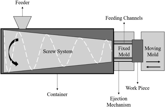
Figure 24.4. Schematic view of an injection molding device.
Biomedical applications such as syringes, inhalers, and insulin measurement pens have also widely used injection molding devices in mass production [2,10]. To obtain well-working medical instrument production with injection molding, Xu et al. have determined some key characteristics [2]. These are:
Review article
Recent developments on nanocellulose reinforced polymer nanocomposites: A review
2.1.1 Injection molding
Injection molding is a solid-state process used to produce materials with complex shapes and excellent surface smoothness. It is suited for polymer granules or mixtures of granules with short fibers that can be mixed and heated within a metallic barrel. The softened material is then transported into the mold cavity using air pressure, among other means [68].
An ideal injection begins with a heated cylinder containing two full cycles of material for injection. As a consequence, some of the material remains inside the machine for twice the residence time. This is called the 50-percent rule. For very sensitive materials, it can be modified to encompass 80% of the injected material. However, the 50-percent rule means that residual materials always remain for longer times within the machine, which can cause degradation [69]. During the preparation of nanocomposites, injection typically occurs after nanoparticles have been dispersed in the matrix material. Masterbatches, extrusion, or both are typically applied previously, to ensure a certain minimum level of dispersion. Injection molding is used as to mold the final shape of the material.
Since the polymers are normally in the molten state, injection provides the prepared samples with good controlled conditions by the control of the injector and mold temperatures and pressures. Some of these parameters were studied by Yousefian and Rodrigue [70] for CNC/polypropylene (PP) composites. Mold temperature modified the capacity for crystallization (such as CNC presence) in the composite because of the different rates of heat transfer to the core of the composite material. Injection temperature was also indicated as an important parameter because it influences the viscosity of the melted polymer, which can modify the alignment of the particles within the matrix and affect many properties of the nanocomposite. The precise control of processing conditions also ensures good reproducibility [71]. Unfortunately, some thermoplastic materials require high temperatures for injection, in order to decrease the viscosity of the melt material and allow injection. In combination with long residence times, such temperatures may damage cellulose nanoparticles.
Chapter
Manufacturing and design of coir fiber composites
7.5.3 Injection molding
Injection molding is a commonly used process for manufacturing of polymer composites reinforced by short fibers, fiber particles or powder [105]. This molding technique consists of three stages; filling, packing/holding and cooling [80]. It is characterized by short cycle time along with post-processing operation/functioning, and dimensional stability to the composite part produced. There are some limitations with the use of injection molding technique, as it requires a lower molecular weight of polymers to maintain a suitable viscosity, the fibers' length and processing temperatures have a low impact on the produced composites performance [8]. In the work described by Haque et al. [47], palm and coir reinforced polypropylene composites were manufactured using a single extruder and injection molding machine. The chemically treated palm/coir composites showed improved mechanical properties compared to the untreated composites, and coir composites exhibited better mechanical properties compared to palm composites.
Hidalgo-Salazar et al. [106] evaluated the properties of polyolefin blend matrix (polypropylene/high-density polyethylene) reinforced with coir fibers. The composites were processed using extrusion followed by injection molding. It was observed that the addition of coir fibers enhanced the mechanical properties and thermal stability of composites without affecting on the polyolefin matrix (PP-HDPE) melting behavior, and also coir fiber showed that it can be an alternative for other additives such as talc, calcium carbonate or foaming agents to reduce the defects of injection molding process. Furthermore, a lot of other studies had utilized injection molding process in fabrication of coir fiber reinforced composites such as Gelfusoa et al. [13] and Haque et al. [92].
Review article
A review on fabrication techniques and tensile properties of glass, carbon, and Kevlar fiber reinforced rolymer composites
2.7 Injection Molding
Injection Molding is a fast, low-pressure, and appropriate process for mass production. During the process of fabrication, sandwich composites are compressed into a mold, and then resin is injected through the pores embedded within the mold [139]. Among the crucial advantages of this fabrication method is the decreased need for surface finishing after the curing and extraction processes.
Chapter
Fabrication, quality and service-life issues for composites in civil engineering
2.2.4 Injection molding
Injection molding is an automated process with very high versatility for production of large runs of relatively complex shapes with a high degree of dimensional accuracy. Although the process is commonly used with thermoplastic resins it can also be used with thermosets. Essentially, injection molding is a high-pressure process in which precompounded molding pellets, consisting of short fibers and encapsulating resin, are fed through a hopper to a screw or ram device. This mechanism conveys the charge through the barrel while subjecting it to strong shearing action that results in a viscous homogeneous mix. The mix is then injected into the mold where it is allowed to cure. Since the mold is closed, complex-shaped parts can be fabricated very rapidly as long as flow of the filled resin can be achieved through the mold. Due to surface effects, fibers next to the mold surface have a preferential alignment parallel to the surface, whereas the orientation away from the surface is random, giving rise to a skin–core morphology. Fiber loadings are generally fairly low and parts are usually for non-structural or secondary structural applications. A number of ancillary structures such as rails, barriers and fittings are routinely made using injection molding.
Chapter
Roadmap for materials selection, processing, and utilization of biocompatible composites in biomedical sectors
6.4.5 Injection molding
This is a plastic injection process and normally uses the thermoplastic resin like PP, polyethylene, and polymethylmethacrylate (PMMA). This process is also utilized for the development of the short fiber-reinforced composites. Injection molding can be performed by injecting resin mixed with fiber into the mold. According to this method, a heated barrel is used to fill the mixed material, injected into the mold cavity, and then allowed to cool and hardened according to the mold dimension. Fig. 6.5 shows the injection molding diagram [25].
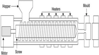
Figure 6.5. Injection molding technique.
Source: With permission from S.-C. Chen. Introduction to injection molding, in: Advanced Injection Molding Technologies (First Edition). Carl Hanser Verlag GmbH & Co. KG, 2019. https://doi.org/10.3139/9781569906040.001.Chapter
Producing Polymer Foams
7.2.2 Injection Molding
Injection molding is a one-time mold process with high productivity and good product quality, and it is applicable to the complex-shaped plastic foam products with high requirements for the dimensions. At the same time, it is also the main method for the production of structural foams. The injection molding can be used for PS, ABS, PE, PP, PVC, styrene-acrylic acid copolymer, and nylon, as well as for the products of light structural materials; industrial products like cold closets, containers, bobbins, vessels; insulation materials; sound/heat insulation materials/products; furniture; construction materials; and woodlike products.
The main facility is the injection molding machine, which includes a plasticizing injecter, mold clamping, and a driving system. Figure 7.1 shows an injection foaming facility with low pressure of N2 injection, and Figure 7.2 shows an injection foaming facility with high pressure [1].